|
| Here is a howto on replacing capacitors on a motherboard. It is equally applicable to replacing capacitors on any computer product pcb. I originally wrote this for the FAQ section of badcaps forums. |
|
|
|
|
|
|
|
|
|
|
|
| It is good to know the history of the board. For instance if the board developed badcaps but was taken out of service early then it is a great candidate for recapping. If the board was left for a very long time and the caps have leaked all over the place then the discharge can probably be cleaned up nice. If the board is now dead having shut down one day then if there is nothing burnt some caps probably failed open and the board is still good for repair. If the board died and there was a burning smell or burnt items on the board then there is a possibility that some caps shorted. |
|
| Testing the board - a Warning! |
|
| If you are given a board to troubleshoot which does not POST, it just blinks the led on the board and the fan twitches, you must be careful that the board is not in a condition which will damage the CPU that you use to test the board. There is a possibility that the VRM chip is damaged because a FET has shorted and therefore Vcore will be too high. The board will be a CPU killer. Better to test Vcore with a multimeter before you attach your CPU to troubleshoot the board. It is always a good idea to test unknown boards with your worst components anyway. |
|
| 2. Practice First and Study the Guidelines |
|
| It is totally possible for you to repair your motherboard yourself but you must read all the info first and also practice before you start your first repair. Even if you have read all the info soldering and replacing caps takes some practice to do nice. It will be VERY satisfying to see your first recapping boot up but dissapointing if it looks sloppy or doesnt work because you did it wrong. |
|
| Get a trash motherboard |
|
| The best thing to do will be to get a trash motherboard and practice removing the caps from it. Learn how to do it gently and you will also learn if your soldering iron is going to be hot enough for the real job. It would be good also to get some of the cheapest caps and practice installing them on the trash board. |
| Learn what is a good solder joint |
|
Learn what is a good solder joint from the following links and practice making one. We guarantee that this will be the most difficult part of the operation but with practice you will learn to do it well.
Elecraft Builder Resources (Click on Soldering Tutorial)
Apogee Kits Downloads (Click on ApogeeKits Free Illustrated Guide to Electronics Soldering)
The Basic Electronics Soldering & Desoldering Guide |
|
| 3. Plan the job before you begin |
|
| Check you have enough caps |
|
| The most important thing is to check that you have enough of the right values of caps to complete the job. When you are done you will be eager to see the board boot and you won't want to wait for another order of caps. Check the original caps on the board again to see if you had missed one or made a mistake with the values. It is very easy to do that. |
|
| Make a Diagram |
|
| Diagram of the board connectors |
|
| It is very good practice when removing a motherboard from the case for any kind of job to make a diagram of the case connector positions (Power Switch, Reset, HDD Led etc) also record the position of each coloured wire. Mark also the position of the primary/secondard IDE, floppy disk, recording the position of the red line on the cable. This makes it so much easier and then you dont have to go hunting for the manual of someones obscure board on the internet when you hooked it up wrong later. Or having to open the damn case again cos you had the hdd led backwards etc. |
|
| Diagram of the position of the caps |
|
| It is very important to make a diagram of the positions and values of the original capacitors on the board. Make sure that you note where the negative lead of each capacitor is on the diagram. The negative lead is marked on the capacitor with a stripe down the side. This stripe matches the white hemisphere around the hole for the negative lead on the board stencil. This diagram is a useful tool also for final checking before you power up the board. It is very important to record the position of the actual negative lead of the original capacitor because the board stencil may be wrong and you want to recheck with the diagram before you install a new capacitor incorrectly. Mark on the diagram the values of the original capacitors and also the values which you will replace each capacitor with if they are different. It is very useful to have this diagram handy during the recapping so you can concentrate on the soldering and not have to think too much or make a mistake |
|
| Mark on the actual board the positions where caps were not installed |
|
| Because of design changes and revisions there may be positions on the board stencil where capacitors were marked to be installed but were not. It is very important to mark on the board with a thin marker pen an X on these positions. It is not recommended to install caps in these positions unless you are following a tried and tested board mod. It is very easy to make a mistake and install caps in these wrong positions so it is nice to see the Xs marked on the board to remind you. |
|
| 4. Prepare your workplace and the board |
|
| Get all your tools handy |
|
 |
|
The minimum you will need is the following. Get it all ready and close to hand. It is a pain when you have to get up and search for something during the job. Get your soldering iron heating up while you are preparing the area. You want to set the iron to 450oC and have it heating up for about 10mins before you begin.
- Soldering Station or Corded Soldering Iron (must be grounded! and at least 40w (60w is a good choice) |
|
|
|
|
| 60w ERSA soldering station. Very important to have a wet sponge to clean the iron when working, whether you get a corded iron or station. |
|
|
|
what you thought was good was useless. 40w is the absolute minimum for recapping. short "standard" chisel tips are recommended because they hold more heat
|
- Solder (60/40, 0.8mm is good) |
|
|
|
solder 60/40 0.8mm
|
|
- Stainless Steel Sewing Needle or Stainless Steel Dental Pick (see later on in the FAQ)
- Desoldering Bulb (if you like)
- Lead Clippers (Fine Wire Cutters) |
|
|
|
pro's kit lead clippers
|
|
| - Board Holder |
| - Flux Cleaner Spray |
|
|
|
Cramolin Flux-Off spray
|
|
- Q-Tips/Cotton Buds (normall used for cleaning your ears)
- Alcohol (95% or best 99-100%) for cleaning electrolyte from the board
- Antistatic Wrist Strap |
|
|
|
anti-static wrist strap
|
|
| For cleaning the lead holes you can use either only the needle/pick or use a desoldering bulb/desoldering braid/desoldering iron (your preference) |
|
| Get the capacitors ready |
|
| Especially if you are working with several values of capacitors it is good to have each value in seperate compartments of one of those plastic boxes with many compartments for organising screws and stuff. This prevents picking up the wrong value and installing it on the board. You can use one of the compartments to put the removed capacitors in. |
|
| Remove all components from the board |
|
| It is pretty obvious but it will get said anyway. You must remove the HSF (CPU Heatsink/Fan), CPU, Ram, and all cards from the board before you start. When you are removing the HSF of a socket processor (non P4 etc) you should place a business card inbetween the bottom of the clip that you will put pressure on and the board. This is because it is quite easy to press too hard and damage the traces. |
|
| Clean the board |
|
| Clean the board of dust on both sides using canned air before you start work. |
|
| Get the board holder ready |
|
An easy to find board holder is two wood clamps, the ones which you use to secure wood to the table for safe sawing. There is probably some in your garage. You can attach them to your work desk upside down and then the board fits in between the handles and the metal guides of the clamps. It is important to have the board secure for removing the caps. If you intend to work with the board between your knees or something, it is not recommended and you will probably burn yourself.
You will want the board holder to be at one side of your workspace and then you want a clear flat area to accommodate the board lying on the table for installing the new caps. Your soldering iron must be in easy reach of both areas and comfortable to work with. |
|
|
|
|
|
|
|
| 5. Removing the Capacitors |
|
| Get your safety glasses on |
|
| When you are soldering you MUST wear safety glasses or your normal prescription glasses. A spatter of hot flux in your eye can injure you seriously. |
|
| Get your antistatic wrist strap on |
|
| You must wear an antistatic wrist strap when you are soldering or handling the board. Put it on the hand holding the iron. The best place to connect the wrist strap is to the back of a computer which is plugged in. |
|
| Get the board holder ready |
|
| The best way for removing capacitors is to put the board on the table with the rear facing up. Then add solder to several caps. Then put it into the board holder to remove the caps. Ideally with the front of the board facing you while you heat from the rear. Otherwise you can hold the board in your knees if you have no board holder. |
|
| Add solder to each lead at the back of the board |
|
It is very important to add a little bit of solder to the leads of the capacitor you are to remove, at the position where the lead meets the board. This will assist you in heating all the solder quickly and easily when you remove the capacitor.
So heat up one of the capacitors leads from the rear of the board so your iron is contacting the pad around the hole and the lead. Then apply a touch of solder to the solder already there. Do the same to the other lead.
It is fastest to do this to a row of capacitors and then concentrate on their removal process. |
|
 |
adding solder to the leads of the existing capacitors
|
|
|
|
solder added and ready for removal.
|
|
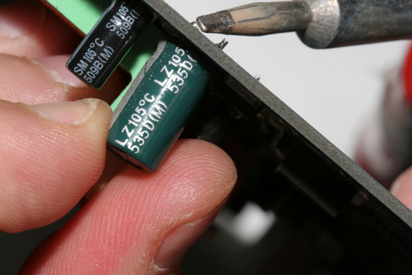
| Remove the capacitor |
|
In order to remove the capacitor, you will heat up one of the capacitors leads from the rear of the board so your iron is contacting the pad around the hole and the lead. Then you will wiggle and push the capacitor towards the other lead while still heating the solder with the iron. Then do the same with the other lead.
You will make your own technique here. Some people like to heat both leads and wiggle them out at the same time. Others like to alternately heat and wiggle each lead until the capacitor is free. Or even get one lead completely out and then work on the other.
It is important to find the best way that removes the capacitor with the least strain. You must make sure that all the solder is nice and hot and dont pull hard but wiggle the lead back and forth a little until it is coming free. If you pull too hard when the solder is not hot enough you can damage the foil of the lead port which runs through the board and makes the connection to the electrical traces. Dont worry just be gentle and you will not harm the board. |
|
|
|
Removing the cap
|
|
| Having Problems to remove the capacitor? |
|
If you are having problems to remove the capacitor then maybe your iron is not hot enough. If it is a 60W then maybe you should try a different sized tip, perhaps the tip is too long and thin and not transferring enough heat from the iron's heater.
Dont forget that if you are working near big traces they suck up the heat from the iron making it difficult to work in that position.
The types of solder used appear to differ with each board manufacturer. Some are easy to heat up, others are not. Older boards are more difficult to work on. Most boards you will have no problem with if your iron is hot enough.
There are different techniques for working on difficult boards. Some like to heat the board with a hot air heat gun or work with hot air pencil. Others like to use large wattage soldering guns for stubborn solder pads. All of these require some experience and knowledge otherwise the board will get trashed. |
|
| Clearing the Hole |
|
Once you have removed the capacitor the hole will not be clean unless you are quite lucky. Some people dont bother to clean the hole but position the leads of the new cap against the holes and then push the cap in at the same time while heating the holes on the back of the board. This not such a great method and it is best to clean the hole first before installing the new cap.
Here we will discuss some methods for cleaning the holes. Really you will have to find the method which works best for you. In order to clean the hole it may help you to have the board held by the board holder. |
|
| Mechanical Solder Pumps |
|
| It is NOT recommended to use a mechanical pneumatic solder pump in order to clean the hole, they really have far too much power. There is a possibility to damage the lead port by sucking it out at the same time as the solder. This would mean that you would have to carefully solder in the new cap, making sure that solder flowed all the way through the hole in order to meet the right traces in the layers of the board. It will be quite difficult so forget about mechanical solder pumps. Additionally the recoil can impact the board and damage a trace or the pump can spray solder debris on the board that can cause a short when you power up the board. |
|
|
|
pneumatic solder pumps. not recommended. if you really have to use them then use them half not full cocked. once you learn a good needle or dental pick technique you will forget about them. they are useful though for removing atx/usb/kbd connectors though
|
|
| Solder Bulb |
|
You could try to clear the hole using a solder bulb which is a device with nozzle and a bulb. The suction is not so powerful as the solder pump but it has enough power to clean the vias. You can use it working with the nozzle on the front of the board and the soldering iron at the back (method 1). Or you could use it working both with the nozzle and the soldering iron at the back of the board (method 2). It is a personal preference again. Some find it difficult to work from both sides of the board at the same time and for that you do need a board holder (others use their knees but you must be careful if you do that). If you were using method 2 you could have the board flat on the table.
(method 1) You place the nozzle flush against the hole on the front of the board while heating the hole with the iron from the rear of the board. You release the iron from the back of the board and then quickly compress the bulb in order to suck the solder out of the hole. You may find this type of desoldering tool useful or not effective.
It is not recommended to use the bulb more than twice on the same hole. If the hole is not then clear after that it is best to proceed to using the dental pick or needle technique. You can also apply a little fresh solder into the hole on the back of the board in order to assist the solder removal process before you use the bulb. |
|
|
|
desoldering bulb
|
|
| Desoldering Wick |
|
| Some people like to use desoldering wick which you place on the hole and then heat it with the iron. Solder will then be drawn and stuck to the wick. You then cut off the part with the solder on periodically to have a fresh bit of wick to work with. Some people like using it, some do not find it useful. |
|
| Desoldering Iron |
|
| If you are doing a lot of cap replacement you may find it useful to buy a desoldering iron from one of the major manufacturers. This will be like a soldering iron but it has a vacuum pump which will suck up the solder through the tip. It will be much easier to work using this type of unit but they are quite expensive. |
|
| Dental Pick or Needle |
|
| Topcat, the owner of badaps.net developed the solution of using a dental pick to clear the holes. This is not a toothpick, it is the hand tool that the dentist uses to scrape inbetween your teeth. You will have to source this from a medical shop or your dentist! It has the benefit of sinking the heat away from the board also. |
|
|
|
perfect sized needle (just bigger than a cap lead) held in part of an electrical block.
|
|
Again like the desoldering bulb there is personal preference, you can either work with the pick on the front of the board while heating from the back or like topcat does work with both the pic and the iron on the back of the board.
So what you will do is heat the hole with the iron until the solder is melted. Then you insert the pick into the hole as far as it will go without forcing it until it emerges from the other side. Then you remove the iron and let the solder harden. Since the pick is stainless steel, the solder will not adhere to it. Then you gently spin and wiggle the pick around until it breaks loose and remove it from the hole. You can use a razor knife to scrape the dry solder from the hole but be careful not to damage a trace on the board. The hole should be clear now. If you do not have access to a dental pick you could use instead a stainless steel sewing needle. It may be useful to have two sizes (one small and sharp, one bigger and rounded tip) which you can hold in an electrical block (the common type used to connect two cables together. |
|
|
|
helping the needle along on a difficult hole by heating from the front
|
|
| So you will make your personal choice of how to clear the holes, the intention is to find a method that will clear the holes fastest as when you heat the pads for a very long time you will damage the board. The most important thing is to have a good hot iron so you go in hot and fast. |
|
| Checking the hole |
|
| It is very useful to have a desk light nearby that you can shine on the back of the board and see if the holes are nice and clean. It is much easier to see that the hole is clean when light is shining through. |
|
|
|
holes cleaned
|
|
| 7. Installing the new capacitors |
|
| Preparing the capacitor for installation |
|
| New capacitors come with quite long leads, it is recommended to trim the leads of a capacitor you are going to install to about 1cm length for both leads. This is not a requirement but it will make it easier for you to insert short leads through the holes rather than unneccessarily long leads. In order to trim the capacitor leads you will use micro clippers not standard wire clippers. This is because the micro clippers cut the wires nicely and do not compress the ends into sharp points like the standard wire clippers. |
|
| Remove the board from the board holder |
|
| In order to install the capacitor you will have the board flat on the table. |
|
| Check for the negative lead carefully before you begin |
|
| Look at the front of the board, you will see a white semi-circle or mark at one side of the circle. You must match up the white/silver/gold line that goes down one side of the capacitor with this white mark. This shows the negative lead. Pay attention to this it is important, the capacitor will blow if installed incorrectly when you apply power to the board. |
|
 |
|
This is where it is useful to refer to the diagram that you made before you started the recapping process. Double check on the diagram the value of the cap to be installed and also double check the polarity. Sometimes the polarity noted on the board stencil is incorrect. Trust the polarity the old capacitor was installed in, rather than the board stencil. Asus for instance indicate positive with the white hemisphere unlike everybody else.
Check also on the front of the board that you have not marked an X to show that a capacitor was not installed in that position. It is easy to get carried away and make that mistake. It is not recommended to install new caps where there were not before unless you are following a tried and tested mod. |
|
| Do not force the capacitor leads down the hole |
|
| You must bend the leads together slightly so they are going to go down both holes nice, do not force the capacitor, if you have problems bend the leads some more or maybe you will have to clean the hole again but better this time. If you force you may damage the foil around the inside of the hole. |
|
| 8. Soldering the capacitor in |
|
Put the capacitor in and then put the board flat on the table with the rear of the board facing you. pull the legs of the capacitor to check that it is tight against the board and bend the legs of the cap slightly outwards. not too much, just enough to hold the cap.
You will heat up both the pad around the hole and also the lead with the iron. You will choose to position the solder at a point where there is an obvious space between the lead and the pad around the hole. Have your iron at the other side. Then you will feed solder into the hole. If you have difficulties heating the lead and pad enough you may touch the solder quickly on the iron and then feed down the hole. |
|
|
|
soldering the new cap in
|
|
| The lead port connects the solder pad through the hole to the pad on the other side of the board and on the way also makes connection to the correct traces for that component on whatever layer of the board required by the design. Therefore it is not necessary to get solder down the hole in order to make a good electrical contact. It is good to get a bit of solder down the hole in order to physically hold the capacitor better on the board. However when you are perfecting your solder techniques you will find that wetting the hole with solder and immediately trying to get solder down the hole makes a much better joint than working only on the solder pad which may give an ugly ball solder joint. |
|
 |
|
| nice shiny solder joints is what you need to see. difficult to take a timer photo and make a nice joint. anyway no more solder than that is what you need. if you solder at 450oC like you removed the cap it is difficult to make a pretty joint. it is fine though. for best performance solder in at 350oC |
|
|
|
|
| Learn what is a good solder joint |
|
You will probably realise that you needed less solder and time than you imagined. Check with the links below and understand what is a good solder joint and then try to make the next one better. This is where technique is difficult to teach. You must understand a good solder joint and then modify your technique until you achieve it. I think that the 450oC may be too hot to achieve a perfect joint though but it is easier to have the iron the same heat as to remove caps. The perfect solder joint is just enough solder to make a good connection. The solder does not make a ball around the solder pad, it curves from the lead in the middle down to the sides of the pad. Dont worry that you did not make a nice joint, as long as the joint is nice and shiny and the solder went down the hole you will learn to make nice solder joints with practice. Do the other lead now.
It is indicated by the manufacturers that if the solder is immediately melted by the iron then the iron is too hot. It should take 1.5-3 seconds to melt the solder. They do not recommend heating for longer than 3 seconds. But dont worry too much about this, concentrate on making a good solder joint and each time you will be faster to solder the cap on. |
|
| Clip the leads |
|
| When you have finished you will use a small pair of wire clippers to clip the excess leads. I recommend the 8PK-30D from Pro's Kit which is a great taiwanese company and not very expensive. Big standard wire clippers will not do a good job, you need proper micro clippers, these are also useful if you want to trim the leads of the capacitor before installing. Clip the leads similarly short as other components on the board. |
|
|
|
leads clipped
|
|
| Do not reheat the solder |
|
| It is not recommended to reheat the solder you have applied to new caps and then apply more if there is a problem. This may result in a worse joint. Better to do the entire process to remove the cap, clean the hole and start again. |
|
| Do not remove and reinstall capacitors an excessive number of times |
|
| The more times you do this you increase the danger of damaging the vias on the board. Also if you heat new capacitors excessively you will damage them, so we want to only heat them once when we solder them in and therefore ensure that they will work at their best. One example of such bad practice would be removing old capacitors from a donor board then reinstalling them into the board you are fixing just to test if it posts and then removing them and installing new good capacitors. Best to install new capacitors the first time and minimise the possibility of damaging the board. |
|
| 9. Finishing the Job - Cleaning the board |
|
When you have finshed you will need to clean the flux from around the solder joints and also the flux splatters which may be around the board. You will need to use a FLUX-OFF spray. I am using one from Cramolin which is called FLUX-OFF and is dimethoxymethane. This will damage plastics and PVC so you will spray a little around the solder joints and manipulate the excess using a cotton bud or Q-tip (normally used for cleaning your ears) so it does not flow down a hole like from the pci slots or whatever to the other side of the board. Then you can rub the excess flux around the joints using the bud. After doing all the joints and checking for ones i have missed i leave the board with a halogen desk lamp (or other hot desk lamp) about a foot from it for 10mins to ensure that all the FLUX-OFF has evaporated. It is highly inflammable so no smoking. The reason you do this cleaning is because some fluxes are mildly corrosive.
If you used solder with no clean flux then you can skip this step. |
|
|
|
If you compare the earlier photos you see the brown flux around the solder joints. it looks like the board is burnt but it is not. after cleaning it looks like this.
|
|
|
|
| When the recapping is done it is important to check the board very well before applying power to it. |
|
| Visually check the board |
|
| Check for little pieces of solder or bits of the leads you have clipped that have stuck to the board and may make a short. I also blast the board on both sides with some canned air for the same reasons. Check the solder pads on the back of the board for the caps that you installed to see that they are not connected by solder to a nearby component and will make a short. It is not good to have a short when you power up the board. |
|
| Check the board against the diagram you made |
|
| See that ALL the capacitors you have installed are the correct values and are installed in the right direction before you apply power to it. Check again that you did NOT install caps in positions where there were not before. |
|
 |
a finished recapping job
|
|
| Apply power to the board |
|
| Connect processor/ram/keyboard/floppy disk and monitor, then power up the board. It is useful to have cpus and ram which are for testing only so you do not fry customers or friends parts if you made a mistake. |
|
| If it does not POST |
|
| Don't jump to the conclusion that you screwed the board on the basis of the boards leds which show a post error or if you do not get a video signal. Stay calm and check your monitor connections, ram seating, cpu seating before you decide you made a soldering mistake. Check the manual for the board leds to see what is the problem. I guarantee that if you were reasonably careful you will get a boot. The boards can take some soldering abuse. If you burnt or scratched some board traces while you were working or have a short that is another thing though. Sometimes clearing the bios using the jumper or taking the battery out can solve problems. |
|
 |
|
 |
damaged traces from excessive heating. not good shots because those are after attempted repair but you get the idea.
|
|
| 11. Run test utilities |
|
| First I would start off booting a ram test utility disk like http://www.memtest86.com/ and checking for ram errors for a few hours while using known GOOD ram, then you can run some burn in utilities like prime95 http://www.mersenne.org/freesoft.htm also in Windows and you would want to see the board totally stable with no errors after running them for some days. At least run the board overnight if you are in a hurry. |
|
| 12. Good luck with your new board |
|
| DIY will make you very happy and you may go on to some other soldering task such as making a stereo amp kit or something. A worthwhile way to pass the weekend and very rewarding. If you progress to doing nice looking cap replacements then you can start doing your friends' boards as well and make some money. If you can do this work then you have nothing to worry about, many component failures are due to bad caps. You could even progress to buying stuff with bad caps for cheap and repairing it yourself. At least you will never worry about buying components with cheap caps again, you will be able to restore them to longevity yourself. |