Showing posts with label projects. Show all posts

Saturday, February 11, 2017

Soldering for Beginners in Electronics

Basic soldering for beginners in electronics. In this article, a pin header is soldered to a LCD which demonstrates how to solder a component to a PCB (printed circuit board).
This is a support article for the Start Electronics Now series of tutorials where the pin header needs to be soldered to the LCD in order to plug it into a breadboard for connection to an Arduino.
See the article on soldering irons before learning to solder.

Safety

Take adequate precautions when soldering – soldering irons get hot and can burn you or your property
Avoid breathing soldering fumes. The lead in solder is poisonous, so always wash your hands after handling solder or solder wire.
Read all safety instructions that are provided with your soldering iron, solder and other equipment.
Here are some precautions to take:
  1. To prevent getting burned, only touch or pick up the soldering iron by the handle, never touch the heating element or tip.
  2. Use a soldering iron stand to prevent burning your desktop or other property.
  3. Work in a well ventilated area. Use a fan to blow the solder fumes away or use a fume extractor.
  4. Remove all flammable materials and liquids from the soldering area.
  5. Wash your hands after handling solder as it contains lead.
  6. Always work in a well lit uncluttered area.
  7. Children are to be supervised by a competent adult when soldering.
Starting Electronics and its authors will not accept responsibility for and damage sustained to yourself or others or any loss or damage to property from following these instructions. If at all unsure, do not proceed.

Preparation

To start soldering, you will need:
  1. A soldering iron and stand with sponge.
  2. Solder.
  3. The items to solder (e.g. component and wire or connector).
  4. A suitable work area with enough light and ventilation.
Wet the soldering iron sponge and then squeeze out the excess water. You will be using the sponge to clean the soldering iron tip.
Switch the soldering iron on or plug it into a power source so that it can start heating up. Place the soldering iron in a soldering iron stand while it is heating. Do not leave the soldering iron unattended while it is heating up or is still hot.

Soldering

To solder a component to a circuit board, first insert the component into the circuit board and then turn it over so that the pins of the inserted component can be seen.
Pick up the soldering iron and unwrap some solder from the solder reel. Heat the pin of the component and the circuit board pad for a second and then apply the solder to the pad and pin. Apply enough solder to make a good joint.
Use the damp sponge in the soldering iron stand to clean the tip of the soldering iron often.
The video below shows how to solder a pin header to a LCD display.
In the video, one pin of the header is soldered (or tacked) to the LCD display. The header is then checked that it is 90° to (at right angles to or square to) the LCD circuit board. The solder joint is reheated to melt the solder so that the header is shifted to 90° to the LCD board.
After soldering one pin and squaring up the header, the pin at the opposite end of the header is soldered and then the header is checked one last time that it is square. The remainder of the pins are then soldered.

First Steps in Using a Multimeter Part 3

A multimeter can be used for continuity testing. Continuity testing is done to check if there is a break in a wire or track on a circuit board (open circuit). Continuity testing can also check whether a wire or track is shorted to another wire or track (short circuit).
When the continuity function is used on a multimeter, the leads of the multimeter are placed on either end of a wire or track, the multimeter will make an audible sound if the wire or track is not broken, i.e. it is continuous. The multimeter acts as a buzzer circuit and the leads act as a switch. When the leads are touched together or on either ends of a conductor, the buzzer circuit is completed and the buzzer sounds.
The videos below show continuity testing on various items. A description of what is being done follows each video.
BASIC CONTINIUITY TESTING

Selecting the Continuity Function

To use the multimeter continuity function, switch the multimeter dial to the continuity test function. Touch the multimeter leads together and you should hear an audible "beep" sound. It is best to always touch the leads together and check for the beep before testing. This is done so that you know that the continuity function is working.

Performing the Continuity Test

In the video, a piece of stripboard is tested to see if a strip is unbroken and also to see that it is not shorted to one of the adjacent strips (one of the strips next to it).
A second multimeter is used to do the same stripboard test. This multimeter has a single dial setting for both the diode test and the continuity test.
A third multimeter (which is a cheap one) does not have an audible continuity tester. In this case, the diode tester is used and continuity is shown on the multimeter's display.
Wires from a cable are then tested for continuity.
Finally a printed circuit board (PCB) is tested for continuity of its tracks and to test that tracks are not shorted to each other. Normally every track would be tested, but only a few are checked in this video for demonstration purposes.

First Steps in Using a Multimeter Part 2

Before measuring current, the positive (red) lead of the multimeter must usually be unplugged from it's normal connector in the multimeter and then plugged into a separate connector in the multimeter that is marked A or mA. This is not always the case, some cheaper meters may have the volts, mill-amps and ohms on one connector and amps on a separate connector.
In this video, two different multimeters are used to measure current in the same circuit. The first multimeter is a cheap one that does not require the red lead to be plugged into a separate connector when measuring mill-amps (mA). The second meter does require the red lead to be plugged into a separate connector to measure mill-amps.

The Circuit Under Test

The circuit in the video in which current is being measured is a simple LED circuit that consists of a LED in series with a resistor. This circuit is the same circuit that is used in tutorial 1.

Precaution

It is very important to realise that when a multimeter is set to the amps or mill-maps scale, and the red lead plugged into the correct socket in the multimeter, that the two leads of the multimeter are now like a single piece of wire. Touching the leads to the two terminals of a battery must never be done as this will short out the battery and is the same as taking a single piece of wire and connecting it across the battery terminals.
In the same way, when the multimeter is set to amps or milli-amps range, it must not be used to measure across any component in a circuit. This would be the same as shorting the component out with a piece of wire.

Taking a Current Measurement

To measure the current flowing in a circuit, the circuit must be broken and the multimeter inserted in the break to then complete the circuit again. In this way the multimeter in current mode forms part of the circuit.
In the video, the current flows from the battery terminal through the multimeter, then through the LED, through the resistor and back to the opposite battery terminal.

Series and Parallel Measurement

The multimeter on the current setting (which makes it into an ammeter) is said to be connected in series in the circuit.
Voltage measurements are made in parallel or across a battery or component in a circuit.

First Steps in Using a Multimeter Part 1

A multimeter is a measuring instrument that anyone involved in electronics will need to use at some stage. A multimeter can be used to measure voltage, current, resistance, continuity and other parameters.

Measuring DC Voltage and Resistance

The video below shows a multimeter being used to measure voltage from batteries (DC (direct current) voltage) and the resistance of some resistors.

Measuring DC Voltage

Selecting the DC Voltage Range

To measure DC voltage using a multimeter, simply turn the selector dial on the multimeter to the DC voltage setting. On an auto-ranging multimeter such as the one shown in the video, there will only be one DC voltage selection on the dial.
A multimeter that is not auto-ranging will have a selection of voltages on the dial that can be chosen, e.g. 2V, 20V, 200V, 1000V. On this type of multimeter, start by selecting the highest voltage on the dial and then turn down to a lower voltage if the voltage measured is seen to be low. If you are measuring a single battery cell and you know that it is a 1.2V or 1.5V cell, then you can start by setting the multimeter dial to 2V or 20V.

Taking a Measurement

After selecting DC voltage on the multimeter dial, use the two probes to measure across the battery terminals. The black probe should be used on the negative terminal of the battery and must be connected to the COM connection on the multimeter. The red probe should be used on the positive terminal of the battery and connected to the connection on the multimeter that is marked V. This connection may have other symbols marking it as well, such as the ohm symbol (Ω).
After applying the probes to the battery, the voltage of the battery will be shown on the multimeter display.

Polarity

If the red and black multimeter probes are connected the wrong way around to the battery (i.e. black on positive and red on negative) then a digital multimeter will show a negative sign next to the voltage reading on the display.
On a digital multimeter, it does not matter if the leads are reversed when measuring voltage. Getting the leads the right way around (correct polarity – red on positive and black on negative) does matter on the old analog multimeters (the type with the indicator needle). An analog (or analogue) multimeter can be damaged if the polarity is reversed on the leads.

Measurement Results

In the video, batteries made up of 1.2V rechargeable cells are used. The first one measured has six cells, so the voltage should be about 1.2V × 6 = 7.2V. The second battery measured contains two cells or 1.2V × 2 = 2.4V. A single 1.2V cell is measured last.
When 1.2V batteries are fully charged, they will have a voltage of slightly more than 1.2V. This can be seen by the measurements taken in the video.


Measuring Resistance

Selecting the Resistance Range (Ohms – Ω)

To measure resistance, using a multimeter, turn the multimeter dial to the ohm marking. As for measuring voltage on an auto-ranging multimeter, there will be only one dial setting for measuring resistance.
On a multimeter that is not auto-ranging, there will be a number of different ranges marked on the multimeter dial, e.g. 200, 2k, 20k, 200k, 2M, 20M. If the approximate range of the resistance to be measured is unknown, then always start measuring with the biggest range, e.g. 20M. If the value measured on this range is seen to be small, then the dial can be turned down to a smaller range.

Precaution

Never measure resistance on a live circuit – i.e. a circuit that has power switched on to it.

Taking the Resistance Measurement

Apply the tips of the multimeter probes across the resistance to be measured and read the resistance value on the multimeter display.

Measurement Results

The resistors measured in the video all have a 5% tolerance. This means that the values of the resistors could be between the 5% more or 5% less than the stated value of the resistor that you would read by decoding the resistor colour code

Wednesday, May 9, 2012

Lab 21: Servo motor control


Discription :

A servo motor is a special geared DC motor equipped with an electronic circuit for controlling the direction of rotation, as well as the position, of the motor shaft. Because servo motors allows precise angular positioning of their output shaft, they are used extensively in robotics and radio-controlled cars, airplanes, and boats to control the motion of their various parts. In this lab session, we will first explore what a servo motor consists of and how it works and then illustrate how to interface it with a PIC microcontroller.
Servo motor control using PIC microcontroller
Theory
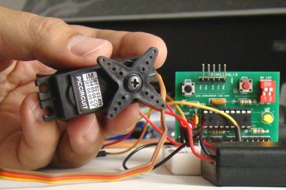
A servo motor (or servo) is a little box that contains a DC motor, an output shaft (servo arm) which is connected to the motor through a series of gears, and an electronic circuit to control the position of the shaft. The objective of using a servo is to achieve precise angular positioning of an object.
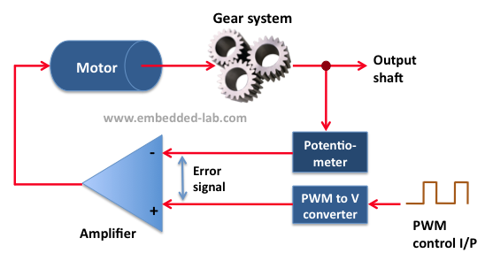
In order to accomplish a servo function, an instantaneous positioning information of the output shaft is fed back to the control circuit using a transducer. A simplest way of doing this is by attaching a potentiometer to the output shaft or somewhere in the gear train. The control electronics compares the feedback signal (which contains the current position of the shaft) from the potentiometer to the control input signal (which contains information of the desired position of the shaft), and any difference between the actual and desired values (known as an error signal) is amplified and used to drive the DC motor in a direction necessary to reduce or eliminate the error. The error is zero when the output shaft gets to the desired position. The functioning block diagram of a typical servomotor is shown below.
Principle of a servomotor
Servo parts (Source: http://tutorial.cytron.com.my/2011/09/19/how-rc-servo-works/)
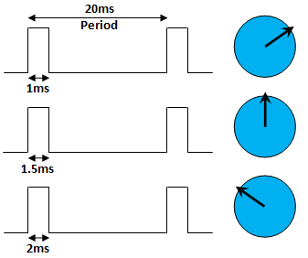
The control input to a servo is a pulse width modulated (PWM) signal, generally of frequency 50 Hz. This means the pulse should repeat every 20ms. The width of the pulse determines the angular position of the output shaft. An electronic circuit inside the servo converts the PWM signal to a proportional output voltage which is compared with the feedback voltage from the potentiometer. If a difference exists between the two, the control circuit drives the motor in an appropriate direction until the difference becomes zero. A typical value of the pulse width is somewhere in the range of 1.0 to 2.0 milliseconds (ms). For a standard servo, a pulse width between 1.0 ms to 1.5 ms makes the servo to turn clockwise (CW), between 1.5 ms to 2.0 ms makes it to turn counterclockwise (CCW), and a 1.5 ms pulse width turns the servo motor to its center. However, these values could vary depending on the brand and make of the motor. It is advised to read the datasheet of the servo to find the true values of the pulse widths required for positioning the servo at different angles.
Most servos rotate through 180°. However. there are some that could rotate through a full 360° or more. Servos are widely used as the moving joints in robotic arms for their precise angular positioning. They also finds applications in radio controlled (RC) toys. For example, in RC cars they are used in the steering mechanisms, and in RC boats to control the rudder.
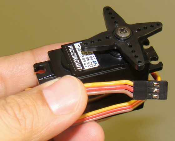
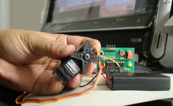
A servomotor has three wires: two are designated for power supply (Vcc and Ground) and the third wire is for the control signal.The Vcc wire is usually red and the ground one is either black or brown. The control signal wire comes in white, yellow, or orange color. The servomotor used in this experiment is from iCircuit technologies and has red, brown, and yellow color wires for Vcc, Gnd, and control signal, respectively. It operates at 5.0 V power supply and provides angular rotation through 180°
A typical servo motor
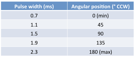
The pulse width values for different angular positions of this servo are provided in the table below. Remember that the repetition rate of the pulse should be 50 Hz (period of 20 ms).
Servo timing information for different anglular positions
Different angular positions of the servo arm
Circuit
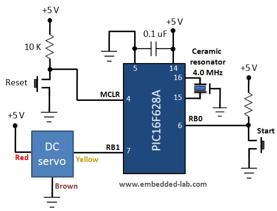
The circuit diagram of this experiment is depicted below. The control input for the servo is derived from the RB1 pin of the PIC16F628A microcontroller that operates at 4.0 MHz using an external ceramic resonator. A tact switch is connected to the RB0 pin to provide user input to control the position of the servo arm. The operation part of this experiment is described in the software section below.
Circuit diagram for servo motor control demonstration
Circuit setup on breadboard
Software
The firmware for PIC16F628A is written in MikroC Pro for PIC compiler. The Timer0 module is operated as timer with prescaler 1:256 to generate an approximate 20 ms gap between the two successive PWM pulses. Keep in mind that the clock frequency is 4.0 MHz, which results into 1 μs machine cycle, thus simplifying the math involved in calculating the delay using Timer0. MikroC provides a built-in library function, Delay_Cyc(), that generates a variable clock cycles delay. This function is used to vary the width of the control pulse from 0.7 to 2.3 ms. When the circuit is first powered up or reset, a 50 Hz PWM signal with 0.7 ms pulse width is continuously generated at RB1 pin. This control signal moves the servo arm clockwise all the way to the end, which is considered as 0 angular position. When the tact switch connected to the RB0 pin is pressed, the width of the pulse is increased by 0.2 ms, which turns the shaft counterclockwise (CCW) by approximately 22.5°. So each time the switch is pressed, the pulse width is increased by 0.2 ms, and the shaft further rotates in CCW direction. After 8 successive presses of the switch, the pulse width becomes 2.3 ms and the shaft reaches the other end (180° angular position). On 9th press, the pulse width is reset to 0.7 ms, and the motor shaft rotates in clockwise direction until it gets at 0 angular position back.
/*
  Lab 21: Servo motor Control using PIC16F628A
  MCU: PIC16F628A running at 4.0 MHz, MCLR enabled, WDT is OFF, Brown out detect disabled
  Written by: Rajendra Bhatt (www.embedded-lab.com)
  2012/03/29
  Description: User input switch is connected to RB0 and Servo Control signal
  is generated from RB1 pin.
*/

sbit SW1 at RB0_bit;
sbit Control at RB1_bit;

unsigned short i=7, delay;

void interrupt() {
  delay = i*10;
  Control = 1;
  Delay_Cyc(delay);  // Generates delay equal to (10*delay) clock cycles
  Control = 0;
  TMR0 = 180;        // TMR0 returns to its initial value
  INTCON.T0IF = 0;   // Bit T0IF is cleared so that the interrupt could reoccur
}

void main() {
 CMCON = 0x07;    // Disable Comparators
 TRISB = 0b00000001;
 PORTB = 0;
 OPTION_REG = 0x07; // Prescaler (1:256) is assigned to the timer TMR0
 TMR0 = 180;        // Timer T0 counts from 180 to 255 to create ~20 ms period
 INTCON = 0xA0;     // Enable interrupt TMR0 and Global Interrupts
 do{
  if(!SW1){         // Change pulse width when Switch is pressed
   Delay_ms(300);
   i = i+2;
   if(i>23) i=7;
  }
 }while(1);
}
Output
After loading the HEX file into the PIC16F628A microcontroller, you can watch the servo controller in action. Watch the demo video at the bottom to see the output of this experiment.

Serial four digit 7-segment LED display module


Discription

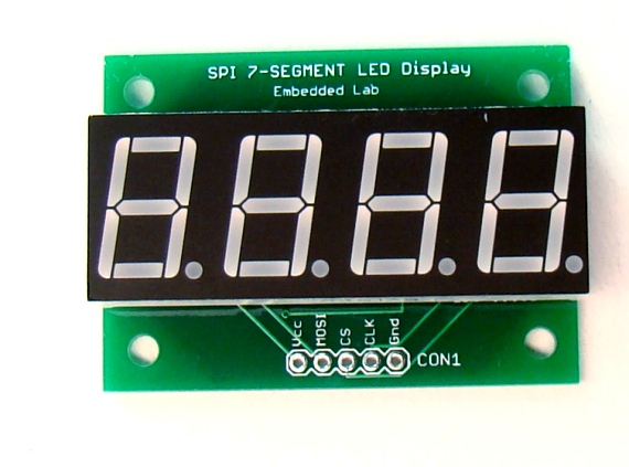
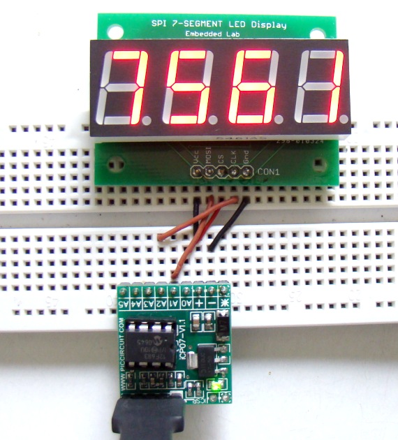
Seven segment LED displays are a very popular mean of displaying numerical information and finds application in front panel display boards of microwave ovens, washers and dryers, digital clocks, frequency counters, and many other gadgets. Compared to the LCD displays, the seven segment LED displays are brighter and provide a far viewing distance and a wide viewing angle. However, the downside is they are resource-hungry. It requires at least 12 I/O pins of a microcontroller to drive a standard 4-digit seven segment LED module. Consequently, their use with low pin-count microcontrollers (such as PIC12F series) is not practically feasible. Here’s a solution for that. The following 4-digit seven segment LED module features a serial interface that requires only 3 I/O pins of a microcontroller and provides full control of all digits and decimal points .
Four digit serial 7-segment LED display
Description
This display module is based on the MAX7219 display driver chip from MAXIM. It provides a serial interface to drive 7-segment LED displays (common-cathode type) up to 8 digits. Included on-chip are a BCD decoder, multiplex scan circuitry, segment and digit drivers, and an 8×8 static RAM to store the digit values. The segment current for all LEDs is set through only one external resistor. However, the device also provides a digital control of the display brightness (16 steps from minimum to maximum) through an internal pulse-width modulator.
Finished
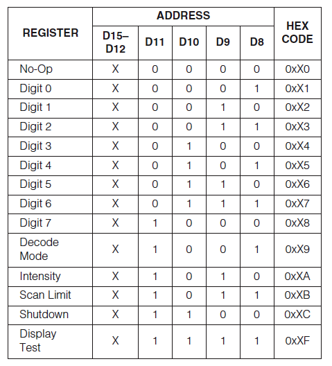
The display module is powered with +5V supply applied to its Vcc pin. Data can be transferred to the display module through SPI interface. Connections are available on the board to access the required signal lines (MOSI, CLK, and CS) for communication between the SPI Master (microcontroller) and the MAX7219 chip. Data is sent in 16-bit packets (two bytes) which is shifted into the internal 16-bit shift register with each rising edge of CLK. The 16-bit packet is labeled as D0-D15, where D0-D7 contain the data, D8-D11 contain the register address, and D12-D15 are don’t care bits. D15 is the most significant bit (MSB) and is the first bit to receive. Although the MAX7219 chip can drive up to 8 digits, only 4 digits are implemented here. They are DIG0 through DIG3, arranged in sequence from the right to the left. The 4-bit addresses (D8-D11) of their corresponding digit registers are 0×01, 0×02, 0×03, and 0×04, respectively. The digit registers are realized with an on-chip 8×8 SRAM, and are addressed directly so that individual digits can be updated at any time. The following table lists the complete addressable digit and control registers of the MAX7219 device.
Register address map of MAX7219
Control Registers
The MAX7219 contains 5 control registers: decode mode, display intensity, scan limit (number of scanned digits), shutdown, and display test (all LEDs on).
Shutdown
On initial power-up, all control registers are reset, and the MAX7219/MAX7221 enters into Shutdown mode. In the shutdown mode, the display is blanked. The D0 bit of the Shutdown register (address 0x0C) must be set to bring the display to normal operation. The same bit can be cleared anytime during operation to enter back into the Shutdown mode. During Shutdown, the contents of the data and control registers are unaltered. Shutdown can be used to save power or as an alarm to flash the display by successively entering and leaving the Shutdown mode.
The MAX7219 device can be put in the Shutdown mode by sending two bytes 0x0C (address) and 0×00 (data) in sequence. Similarly, 0x0C followed by 0×01 brings it back to normal operation.
Decode-Mode
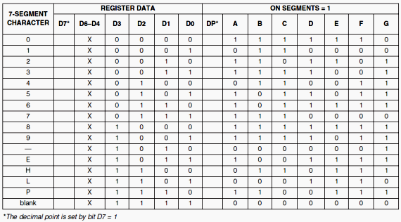
The decode-mode register (address 0×09) sets BCD code B (0-9, E, H, L, P, and -) or no-decode operation for each digit. Each bit in the register corresponds to one digit. A logic high selects code B decoding while logic low bypasses the decoder. When the code B decode mode is used, the decoder looks only at the lower nibble of the data in the digit registers (D3–D0), disregarding bits D4–D6. The D7 bit is independent of the decoder and turns the decimal point on if it is set (D7=1). For example, sending bytes 0×02 and 0×05 in sequence sets the DIG1 (second digit from the right) to display decimal 5. Similarly, 0×01 followed by 0×89 displays decimal 9 at DIG0 with its decimal point set. The following table provides the complete list of the code B font.
Code B font
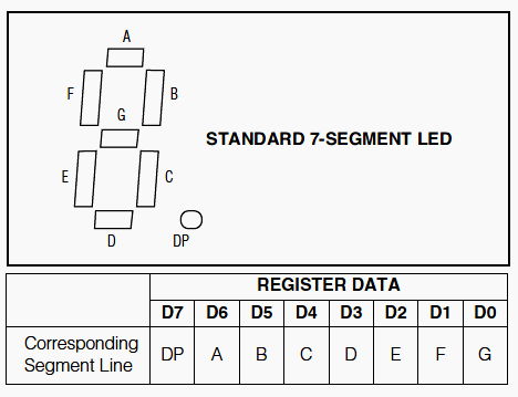
When no-decode is selected, data bits D7–D0 correspond to the segment lines (A-G and DP) of the seven segment display.
No-Decode Mode Data Bits and Corresponding Segment Lines
Intensity control
The MAX7219 allows display brightness to be controlled through software by an internal pulse-width modulator (PWM). The PWM output is controlled by the lower nibble (D3-D0) of the intensity register (address 0x0A) and allows 16 brightness levels. The zero nibble value sets the display intensity to minimum, whereas all nibble bits set to 1 selects the maximum intensity level for the display.
Scan-Limit
The scan-limit register (address 0x0B) sets how many digits are to be displayed from 1 to 8. For a 4-digit display, the scan-limit register value should be set to 0×03.
Display-Test
The display-test register has address 0x0F and allows to turn all LEDs on by overriding, but not altering, the values of the control and digit registers. In order to enable the display-test mode, the D0 bit of the display-test register must be set. The same bit must be cleared to get back to the normal operation.
Interfacing with a microcontroller
The serial 7-segment LED display module can be interfaced with any microcontroller that has 3 I/O pins available. If the microcontroller features a built-in hardware SPI, then the display module can be interfaced as a SPI slave device. In that case the SPI signal lines SDO (serial data out), SCLK (serial clock), and SS (slave select) from the microcontroller can be directly connected to the MOSI, CLK, and CS pins labeled on the display module. CS is active low signal.
In case the host microcontroller doesn’t have a hardware SPI module, the interface can be implemented in software. The SPI communication starts with holding CS pin LOW and then sending 16 bits of data serially (MSB first) over the MOSI pin at the rising edge of CLK signal, and finally pulling the CS pin back to HIGH. The following example illustrates how to write a software SPI routine to drive the display module with three general purpose I/O pins of the PIC12F683 microcontroller. The program is written in mikroC Pro for PIC compiler but can be easily modified for other high-level compilers. The GP0, GP1, and GP2 pins of the PIC12F683 drives the CS, MOSI, and CLK pins, respectively, of the 7-segment display module to create a 4-digit up-counter. The counter counts from 0000 to 9999 and then reset to zero and start again.
// Define Soft-SPI connections
#define CS_Pin       GP0_bit
#define MOSI_Pin     GP1_bit
#define CLK_Pin      GP2_bit

void SPI_Write_Byte(unsigned short num){
 unsigned short t, Mask, Flag;
 CLK_Pin = 0;
 Mask = 128;
 for (t=0; t<8; t++){
  Flag = num & Mask;
  if(Flag == 0) MOSI_Pin = 0;
  else MOSI_Pin = 1;
  CLK_Pin = 1;
  CLK_Pin = 0;
  Mask = Mask >> 1;
 }
}

void MAX7219_INIT() {
  // Disable Shutdown mode
  CS_Pin = 0;              // CS pin is pulled LOW
  SPI_Write_Byte(0x0C);    // Select Shutdown register
  SPI_Write_Byte(0x01);    // Set D0 bit to return to normal operation
  CS_Pin = 1;              // CS pin is pulled HIGH

  // Set BCD decode mode for digits DIG0-DIG3
  CS_Pin = 0;              // CS pin is pulled LOW
  SPI_Write_Byte(0x09);    // Select Decode Mode register
  SPI_Write_Byte(0x0F);    // Select BCD mode for digits DIG0-DIG3
  CS_Pin = 1;              // CS pin is pulled HIGH

  // Set display brighness
  CS_Pin = 0;              // CS pin is pulled LOW
  SPI_Write_Byte(0x0A);    // Select Intensity register
  SPI_Write_Byte(0x0F);    // Set maximum brightness
  CS_Pin = 1;              // CS pin is pulled HIGH

   // Set display refresh
  CS_Pin = 0;              // CS pin is pulled LOW
  SPI_Write_Byte(0x0B);    // Select Scan-Limit register
  SPI_Write_Byte(0x03);    // Select digits DIG0-DIG3
  CS_Pin = 1;              // CS pin is pulled HIGH

 // Enable Display-Test
  CS_Pin = 0;              // CS pin is pulled LOW
  SPI_Write_Byte(0x0F);    // Select Display-Test register
  SPI_Write_Byte(0x01);    // Enable Display-Test
  CS_Pin = 1;              // CS pin is pulled HIGH

  Delay_ms(1000);
 // Disable Display-Test
  CS_Pin = 0;              // CS pin is pulled LOW
  SPI_Write_Byte(0x0F);    // Select Display-Test register
  SPI_Write_Byte(0x00);    // Disable Display-Test
  CS_Pin = 1;              // CS pin is pulled HIGH

}

 void Display_Counter(unsigned int j){
  CS_Pin = 0;                    // CS pin is pulled LOW
  SPI_Write_Byte(4);             // Send thousands digit
  SPI_Write_Byte((j/1000)%10);
  CS_Pin = 1;                    // CS pin is pulled HIGH

  CS_Pin = 0;                    // CS pin is pulled LOW
  SPI_Write_Byte(3);             // Send hundreds digit
  SPI_Write_Byte((j/100)%10);
  CS_Pin = 1;                    // CS pin is pulled HIGH

  CS_Pin = 0;                    // CS pin is pulled LOW
  SPI_Write_Byte(2);             // Send tens digit
  SPI_Write_Byte((j/10)%10);
  CS_Pin = 1;                    // CS pin is pulled HIGH

  CS_Pin = 0;                    // CS pin is pulled LOW
  SPI_Write_Byte(1);             // Send ones digit
  SPI_Write_Byte(j%10);
  CS_Pin = 1;                    // CS pin is pulled HIGH
 }

unsigned short i;
unsigned int counter = 0;

void main() {
  TRISIO=0b00001000;        // GP3 is input only
  CMCON0 = 0x07;
  ANSEL = 0x00;
  MAX7219_INIT();           // Initialize  MAX7219
  do{
   for (counter=0; counter<10000; counter++) {
    Display_Counter(counter);
    Delay_ms(1000);
   }
  }while(1);
}
The PIC12F683 microcontroller runs at 4.0 MHz internal clock and MCLR is disabled. In the picture below, the tiny PIC12F683 board is from iCircuit Technologies.
4-digit UP-counter using PIC12F683
The LED display module can also be interfaced with Arduino board using the LedControl library.
Interfacing with Arduino
Summary
This MAX7219 based LED display module allows you to interface a 4-digit 7-segment LED display to low-pin count microcontrollers using only three I/O pins. It gives you full control of all digits, decimal points, and the display brightness.
This display module is available for purchase as a kit. The price of the kit is $10.99 and includes free shipping (regular USPS) within the continental United States. The payment will be through Paypal. If you want this kit, email me first at admin (at) embedded-lab.com, and I will send you my Paypal information.
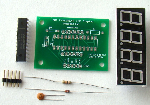
The picture below shows what you will get in the kit. A 5-pin male header (straight) is included in the kit. Here are the assembly instructions.
4-digit serial seven segment LED display kit

Monday, January 30, 2012

control humidity and temperature


Discription :

Measurement and control of temperature and relative humidity finds applications in numerous areas. These days devices are available which have both temperature and humidity sensors with signal conditioning, ADC, calibration and communication interface all built inside them. The use of such smart sensors greatly simplify the design and reduces the overall cost. We discussed in past about Humidity and temperature measurements with Sensirion’s SHT1x/SHT7x sensors. These sensors are capable of measuring both temperature and relative humidity and provide fully calibrated digital outputs. While  SHT1x/SHT7x are very accurate sensors, they are still expensive for hobbyists use. This articles discusses the DHT11 sensor which also provides calibrated digital outputs for temperature and humidity but is relatively lot cheaper than the Sensirion sensors. The DHT11 sensor uses a proprietary 1-wire protocol which we will be exploring here and implementing with the PIC16F628A microcontroller that will receive the temperature and humidity values from the sensor and display them on a 16×2 character LCD.
Interfacing DHT11 sensor with PIC16F628A
About DHT11 sensor
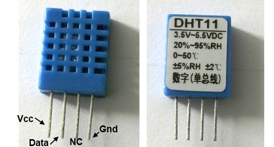
The DHT11 sensor comes in a single row 4-pin package and operates from 3.5 to 5.5V power supply. It can measure temperature from 0-50 °C with an accuracy of ±2°C and relative humidity ranging from 20-95% with an accuracy of  ±5%. The sensor provides fully calibrated digital outputs for the two measurements. It has got its own proprietary 1-wire protocol, and therefore, the communication between the sensor and a microcontroller is not possible through a direct interface with any of its peripherals. The protocol must be implemented in the firmware of the MCU with precise timing required by the sensor.
DHT11 sensor comes in a single row 4-pin package
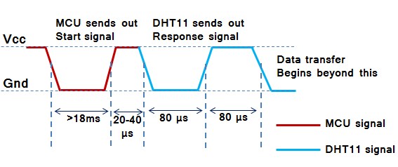
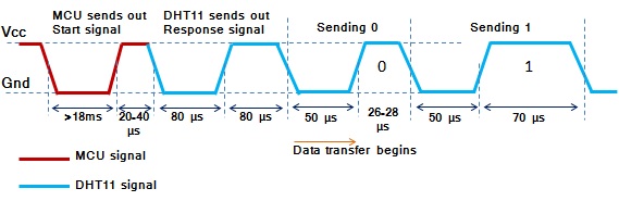
The following timing diagrams describe the data transfer protocol between a MCU and the DHT11 sensor. The MCU initiates data transmission by issuing a “Start” signal. The MCU pin must be configured as output for this purpose. The MCU first pulls the data line low for at least 18 ms and then pulls it high for next 20-40 μs before it releases it. Next, the sensor responds to the MCU “Start“  signal by pulling the line low for 80 μs followed by a logic high signal that also lasts for 80 μs. Remember that the MCU pin must be configured to input after finishing the “Start“ signal. Once detecting the response signal from the sensor, the MCU should be ready to receive data from the sensor. The sensor then sends 40 bits (5 bytes) of data continuously in the data line. Note that while transmitting bytes, the sensor sends the most significant bit first.
"Start" and "Response" signals
The 40-bit data from the sensor has the following structure.
Data (40-bit) = Integer Byte of RH + Decimal Byte of RH + Integer Byte of Temp. + Decimal Byte of Temp. + Checksum Byte
For DHT11 sensor, the decimal bytes of temperature and humidity measurements are always zero. Therefore, the first and third bytes of received data actually give the numeric values of the measured relative humidity (%) and temperature (°C). The last byte is the checksum byte which is used to make sure that the data transfer has happened without any error. If all the five bytes are transferred successfully then the checksum byte must be equal to the last 8 bits of the sum of the first four bytes, i.e.,
Checksum = Last 8 bits of (Integer Byte of RH + Decimal Byte of RH + Integer Byte of Temp. + Decimal Byte of Temp.) 
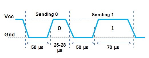
Now lets talk about the most important thing, which is signalling for transmitting “0″ and “1″. In order to send a bit of data, the sensor first pulls the line low for 50 μs. Then it raises the line to high for 26-28 μs if it has to send “0″, or for 70 μs if the bit to be transmitted is “1″. So it is the width of the positive pulse that carries information about 1 and 0.
Timing difference for transmitting "1s" and "0s"
Start, Response and Data signals in sequence
At the end of the last transmitted bit, the sensor pulls the data line low for 50 μs and then releases it. The DHT11 sensor requires an external pull-up resistor to be connected between its Vcc and the data line so that under idle condition, the data line is always pulled high. After finishing the data transmission and releasing the data line, the DHT11 sensor goes to the low-power consumption mode until a new “Start” signal arrives from the MCU.
Circuit diagram
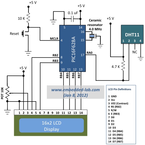
Here is the circuit diagram showing the DHT11 sensor and a HD44780-based character LCD interfaced to the PIC16F628A microcontroller. The microcontroller runs at 4.0 MHz clock using an external resonator connected between OSC1 (16) and OSC2 (15) pins. The use of 4.0 MHz clock makes the timing calculation easier as 1 machine cycle becomes 1 μs. The timing information will be used to calculate the width of the received data pulse from the sensor so that we could identify if it is carrying a 1 or 0.
Circuit connections for PIC16F628A and DHT11 sensor
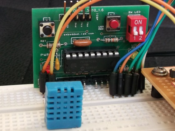
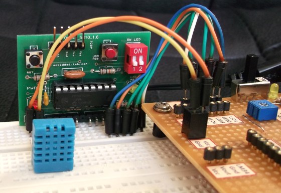
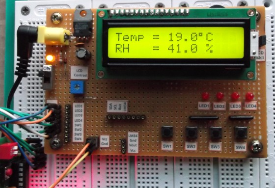
The following pictures show the circuit setup on a breadboard. Don’t get confused with the four LEDs and tact switches shown on the perforated board. They have nothing to do with this project. They are there because I am using my DIY Experimenter’s I/O board for the LCD part of this project. Similarly, I am using my 18-pin PIC16F board for easy prototyping with the PIC16F628A microcontroller.
Complete setup of the circuit
PIC16F628A module and the DHT11 sensor are plugged into the breadboard
Software
Writing a software for DHT11 sensor is little more challenging than the hardware part because of the timing conditions for 1s and 0s. I have written sub-routines in mikroC Pro for PIC for initializing the DHT11 sensor and reading the 40-bit of data in sequence. I have used Timer2 module to keep track of the width of the received data pulse, which is required to identify if the received bit is 1 or 0. When a low-to-high pulse is detected at the beginning of any data bit, TMR2 is cleared and turned ON. Since the clock frequency used here is 4.0 MHz, the TMR2 increments by 1 in every 1 μs. The TMR2 is stopped whenever the data pulse is low again. The value of the TMR2 register gives you the the width of the data pulse in μs. I am using 40 μs as the threshold for identifying 0 and 1. If the TMR2 is greater than 40, it means the received bit is 1, else it is 0. Here is the complete source code written in mikroC Pro for PIC. It can be easily adapted to any other platform, but remember that if you are using a different clock frequency you should have to modify the timer operation accordingly.
// LCD module connections
sbit LCD_RS at RB2_bit;
sbit LCD_EN at RB3_bit;
sbit LCD_D4 at RB4_bit;
sbit LCD_D5 at RB5_bit;
sbit LCD_D6 at RB6_bit;
sbit LCD_D7 at RB7_bit;
sbit LCD_RS_Direction at TRISB2_bit;
sbit LCD_EN_Direction at TRISB3_bit;
sbit LCD_D4_Direction at TRISB4_bit;
sbit LCD_D5_Direction at TRISB5_bit;
sbit LCD_D6_Direction at TRISB6_bit;
sbit LCD_D7_Direction at TRISB7_bit;

sbit Data at RA0_bit;
sbit DataDir at TRISA0_bit;
char message1[] = "Temp = 00.0 C";
char message2[] = "RH   = 00.0 %";
unsigned short TOUT = 0, CheckSum, i;
unsigned short T_Byte1, T_Byte2, RH_Byte1, RH_Byte2;

void StartSignal(){
  DataDir = 0;     // Data port is output
  Data    = 0;
  Delay_ms(25);    // Low for at least 18us
  Data    = 1;
  Delay_us(30);    // High for 20-40 us
  DataDir = 1;     // Data port is input

}

unsigned short CheckResponse(){
  TOUT = 0;
  TMR2 = 0;
  T2CON.TMR2ON = 1;      // Start TMR2 while waiting for sensor response
  while(!Data && !TOUT); // If there's no response within 256us, the Timer2 overflows
  if (TOUT) return 0;    // and exit
  else {
   TMR2 = 0;
   while(Data && !TOUT);
   if (TOUT) return 0;
   else {
    T2CON.TMR2ON = 0;
    return 1;
   }
  }
}

unsigned short ReadByte(){
  unsigned short num = 0, t;
  DataDir = 1;
  for (i=0; i<8; i++){
   while(!Data);
   TMR2 = 0;
   T2CON.TMR2ON = 1;  // Start TMR2 from 0 when a low to high data pulse
   while(Data);       // is detected, and wait until it falls low again.
   T2CON.TMR2ON = 0;  // Stop the TMR2 when the data pulse falls low.
   if(TMR2 > 40) num |= 1<<(7-i);  // If time > 40us, Data is 1
  }
  return num;
}

void interrupt(){
  if(PIR1.TMR2IF){
   TOUT = 1;
   T2CON.TMR2ON = 0; // stop timer
   PIR1.TMR2IF  = 0; // Clear TMR0 interrupt flag
  }
}

void main() {
  unsigned short check;
  TRISB = 0b00000000;
  PORTB = 0;
  TRISA = 0b00100001;
  CMCON = 7;
  INTCON.GIE = 1;    //Enable global interrupt
  INTCON.PEIE = 1;   //Enable peripheral interrupt
  // Configure Timer2 module
  PIE1.TMR2IE = 1;  // Enable Timer2 interrupt
  T2CON = 0;        // Prescaler 1:1, and Timer2 is off initially
  PIR1.TMR2IF =0;   // Clear TMR INT Flag bit
  TMR2 = 0;
  Lcd_Init();
  Lcd_Cmd(_Lcd_Clear);
  Lcd_Cmd(_LCD_CURSOR_OFF);

  do {
    Delay_ms(1000);
    StartSignal();
    check = CheckResponse();
    if (!check) {
     Lcd_Cmd(_Lcd_Clear);
     Lcd_Out(1, 1, "No response");
     Lcd_Out(2, 1, "from the sensor");
    }
    else{

     RH_Byte1 = ReadByte();
     RH_Byte2 = ReadByte();
     T_Byte1 = ReadByte();
     T_Byte2 = ReadByte();
     CheckSum = ReadByte();
     // Check for error in Data reception
     if (CheckSum == ((RH_Byte1 + RH_Byte2 + T_Byte1 + T_Byte2) & 0xFF))
     {
      message1[7]  = T_Byte1/10 + 48;
      message1[8]  = T_Byte1%10 + 48;
      message1[10] = T_Byte2/10 + 48;
      message2[7]  = RH_Byte1/10 + 48;
      message2[8]  = RH_Byte1%10 + 48;
      message2[10] = RH_Byte2/10 + 48;
      message1[11] = 223;     // Degree symbol
      Lcd_Cmd(_Lcd_Clear);
      Lcd_Out(1, 1, message1);
      Lcd_Out(2, 1, message2);
      }

      else{
       Lcd_Cmd(_Lcd_Clear);
       Lcd_Out(1, 1, "Checksum Error!");
       Lcd_Out(2, 1, "Trying Again ...");
      }
    }

  }while(1);
}
You can also simplify the ReadByte subroutine without using the Timer2 module. The following version of ReadByte subroutine works equally well. Once the data pin is detected high, wait for 40 μs and check the data line again. If it is still high, it is 1, else 0.
unsigned short ReadByte(){
  unsigned short num = 0, t;
  DataDir = 1;
  for (i=0; i<8; i++){
   while(!Data);
   Delay_us(40);
   if(Data) num |= 1<<(7-i);
   while(Data);
   }
  return num;
}
Output
The accuracy of DHT11 is not as good as Sensirion’s SHT1X/7X series sensors, but it provides an easy and cheap solution to hobbyists for measuring relative humidity and temperature in parallel using a single device, which is sometime required in certain applications such as calculating the dew point.
Temperature and relative humidity measured by DHT11 sensor